 A while ago I spotted the Open Workbench Logic Sniffer on Hackaday. A logic sniffer . analyser is a useful tool have around the place and at ~$50 with some flying leads to make it up to the free shipping threshold. Seeing as it arrived the other day I thought I would share my first impressions of it…
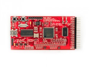
The Board
The system comes shipped as a bare board – so I need to get some self adhesive rubber feet for it really – I will also keep my eye out for a potential case as well.
The main components is a Xilinx Spartan FPGA. The whole thing is based on the SUMP FPGA base logic analyser – so no big surprises that this is the main work horse!
It also has a Microchip 18F24 which looks like it is handling the USB interface.
The board also has several non-populated through hole headers which are for PIC ICSP, FPGA JTAG and some kind of expansion pins (as well as a set of four labelled TRG1 CK1 TRG0 and CK0). There is also a populated set of ROM ISP headers and what looks like some UART pin headers.
Alongside all this we have a number of indicator LEDs for ARM, Trigger, Power and USB Activity. Also some buttons for update and reset actions.
At the end of the board we have the analyser bus. This has a GND connection at both ends and 16 signals available for connecting flying leads to. The signals are fed into a LCX16245 – which is a low voltage bidirectional buffer (so in theory the FPGA could drive the the signals out if you wanted to re-purpose the board!)
Anyway, for more detailed information on the project see the Gadget Factory page – this has the user guide, schematics, board design and software on it as well as installation videos and a video tutorial on UART analysis (something I will be trying soon!).
Installation
Once I had dug out a USB A to Mini-B cable and downloaded the software I was set to go. I had tried getting it to run on Linux (Ubuntu 10.04), but I gave up after about 20 minutes of fiddling and getting nowhere and decided to revert to good old windows XP – so if anyone has any easy to follow instructions on that one let me know!
After extracting the archives I plugged in the device, at which point windows requests a driver. Find the inf folder from the OpenLogic binaries archive, select that and the correct driver will be installed. This creates a virtual COM port. The number of the COM port can be found in the Device Manager (it is the one with Manufacturer = “Microchip Technology, Inc.” and Location = “Location 0 (CDC RS-232 Emulation Demo)”).
Once this is installed run the OB_Logic_Sniffer.exe file and you get the client.
Select Device -> Capture and you get the Capture setup menu. This enables you to setup triggers, sampling rate and recording size.
Testing
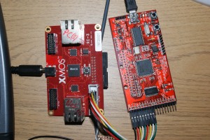
To test it I grabbed my XMOS XC-3 and connected 8 of the the lines to the GPIO port (XS1_PORT_8C on Core 0). I wrote a simple XC program to simply count up in a sequence continuously in a loop at 25Mhz. Here is the setup I used for testing.
After fiddling around wondering why Bank 1 wasn’t working, I enabled all the banks and discovered that the signals were on bank 3 (channels 16 -24). I have no idea why this is… but hey ho. It is working and the output is below.
Conclusion
Overall this has the all the makings of a strong tool. It is very affordable @ $45 shipped (available from Seeed Studio) and 16/32 channels of logic analyser @ 100MSPS is certainly not to be sniffed at.
Quality of the software is one of the most important things in a logic analyser as without good analysis software they are a waste of time. The Logic Sniffer doesn’t disappoint in this area- It has the capabilities to do simple single trigger or a complex 4 stage triggering and the analyser Java based client is easy and intuitive to use. While basic in the professional logic analyser world they are pretty good for most peoples needs. Extension of the triggering modes would be well worth the development time. Also simple improvements such as the ability to type in Hex values would be nice, rather than having to build a trigger mask with tick boxes.
Alongside the triggering features is the systems ability to analyse SPI, I2C and UART signals. Expanding this protocol analysis is something that should be actively worked on, though it has a good base (these features will hopefully be subject to another review at a later date).
However, the project in its entirety is currently it is a little rough around the edges. A couple of pointers for simple improvements would be:
- an integrated installer – especially the windows stuff. It’s a small point, but they aren’t hard to make and it makes the whole software installation process a lot less painful (rather than downloading two zips and having to extract them!)
- a simpler firmware upgrade process ( i.e. more integrated PC side software) – the current one looks fairly daunting (even for someone like me who is a relatively experienced user of embedded hardware).
Over all, as an open source hacking tool, I would give this project 8/10, a few minor improvements would push it up. Open source hardware like this can be functionally good, but is often let down by the lack of polish in the user experience.


Thanks for the comment about inputs being 16 to 32 and not 0 to 15. Just started testing unit . Doing my nut about lack of response of unit
Thank you for your review, really useful. I am thinking about buying one of those, but I can’t seem to find the size (millimeters) of the PCB. Could you share? Thanks!
Unfortunately I haven’t got the board to hand at the moment… didn’t the project release the design files. I thought it was all completely open sourced?
I received my board a few days ago and have been playing with it. The software is minimal but functional. For $50, it is still a bargain for a 200mhz logic recorder. It would be nice to see better and bigger software. I hope future development continues.