The “Thats the warranty gone…” aka as a ‘teardown’ post!
With the UART TX not working properly I was forced to open it up… so here is a bit of analysis and some photos of what is inside for the curious!
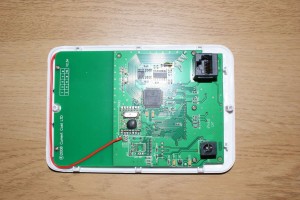
The device is pretty easy to open up – there are 3 clips down each side of the plastic case. Once those are popped out the front of the unit comes away with the board firmly attached to it. Above is the photo of the board after opening it initially.
This shows a PIC microcontroller (18F85J90) . There is also a receiver module on the board – most likely a ZigBee unit (Current Cost have a Zigbee logo on their website!) . Apart from that there is just the power regulator (a tiny thing on next to the power plug).
It is also interesting to note that there is a set of footprints that are unpopulated that look like they should be for a transmitter (the big clue is the ANT pad!). This might be the same zigbee configuration, but made up of discrete components as the circuit layout (particularly the LC filter arrangement connected to the antenna!) are remarkably similar. Also, the box is marked RX1 as is the Zigbee module. Maybe this is done as a cost reduction option if the separate modules weren’t cheap enough or available?
The rest of the IC’s look like memory – so nothing too exciting there.
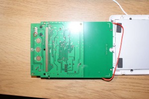
So to the other side of the board is basically componentless – apart from the LED and the contacts for the display (massive IO hog!) and the buttons.
What I did confirm is that the following pins are connected on the RJ45 (there are some others, but I couldn’t be bothered to put the effort in at this stage to get the data sheet out for the PIC and work out where they were going!):
- pin 1 is the unregulated +3V from the power unit
- pin 4 goes into the GND plane
- pins 7 and 8 are RX and TX
What was particularly annoying was the solder bridge (blob really!) I located between pin 8 and the via near it. This explained the 0’s I was getting on my data line!


Pingback: Energy Monitor – part 2 « Silly Science
That looks like a HopeRF RFM12B transceiver. Operating at 433 MHz, judging from the antenna wire length. See http://www.hoperf.com/rf_fsk/rfm12b.htm – it’s the same module I use, see http://cafe.jeelabs.net/lab/jn4/
ZigBee is a protocol. So they are probably using the ZigBee protocol through the RFM12B. There is an open source implementation at http://freaklabs.org/index.php/FreakZ-Open-Source-Zigbee-Stack.html
You post awsome articles, i have bookmarked for future referrence !
I feel really glad after I discovered this site!
Which is the thermistor for the internal temp sensor? I’d rather be able to remove it, add some long wires, attach the thermistor and put it outside. I’m much more interested in how temperature outside will affect my energy usage, not inside temp. Is it that little silver cylinder?
Yeah I think you are right. I don’t have the board to hand (or apart anymore! its in use on my desk) – but the only other thing I could think that it would be the crystal for the microcontroller, but I think that the microchip part will most likely use internal oscillator.
I believe the rf modules uses are the RFM01 (rx) and RFM02 (tx) from hoperf and not the RFM12(B)