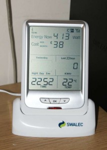
 My energy monitor arrived today! It’s working well – I was slightly worried about how good the reception would be for the transmitter, but I am pleasantly surprised that even with the receiver 3 floors above the transmitter it seems to register a good signal.
But that’s boring – time to start hacking!
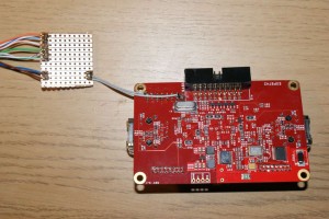
So, first thing I need is the interface cable. The back of the unit has a handy RJ45 connector that has serial in it (see my initial energy monitoring post). This needs connecting to my XC-3 kit so that I can begin to get the data out of it. So time to get the soldering iron out!
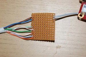
So, initially all I need are two wires from the RJ45 network cable (standard network wiring configuration)-
- Brown = the UART transmit (from the energy monitor)
- Blue = ground
I soldered the rest of them onto the strip board in case I wish to use them later and it keeps things neat and tidy.
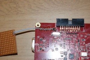
For the moment I am using the the GPIO port on the XC-3, using pin 1 for a 1 bit port (XCore UART RX) and pin 16 is ground. This should give a good base from which to work. Eventually I would like to put it on the LED connectors to keep the GPIO free. The other bonus of using the LED connector is that the output side is buffered up to 5V which is what the UART on the energy monitor needs – though I think I will have a check of the Microchip PIC they use inside and see if it will take 3.3V logic levels.
Next time… getting data into the XC-3


Whatever really stimulated you to write “Energy Monitor – Part 1